Projects -- 50 PoleThe first question is "why?" The short answer is, that while most people fantasize about living off-grid (and making their own power), in Kanata we frequently do live off-grid (without power). So, when the PABX gets shut off, there are no telephones. This project is an "emergency bypass" switch that routes a large number of the lines in the house to several of the trunks in case of power failure. The following details the construction phase of the project. Mounting and wiring the relays S
M
L
XL
S
M
L
XL
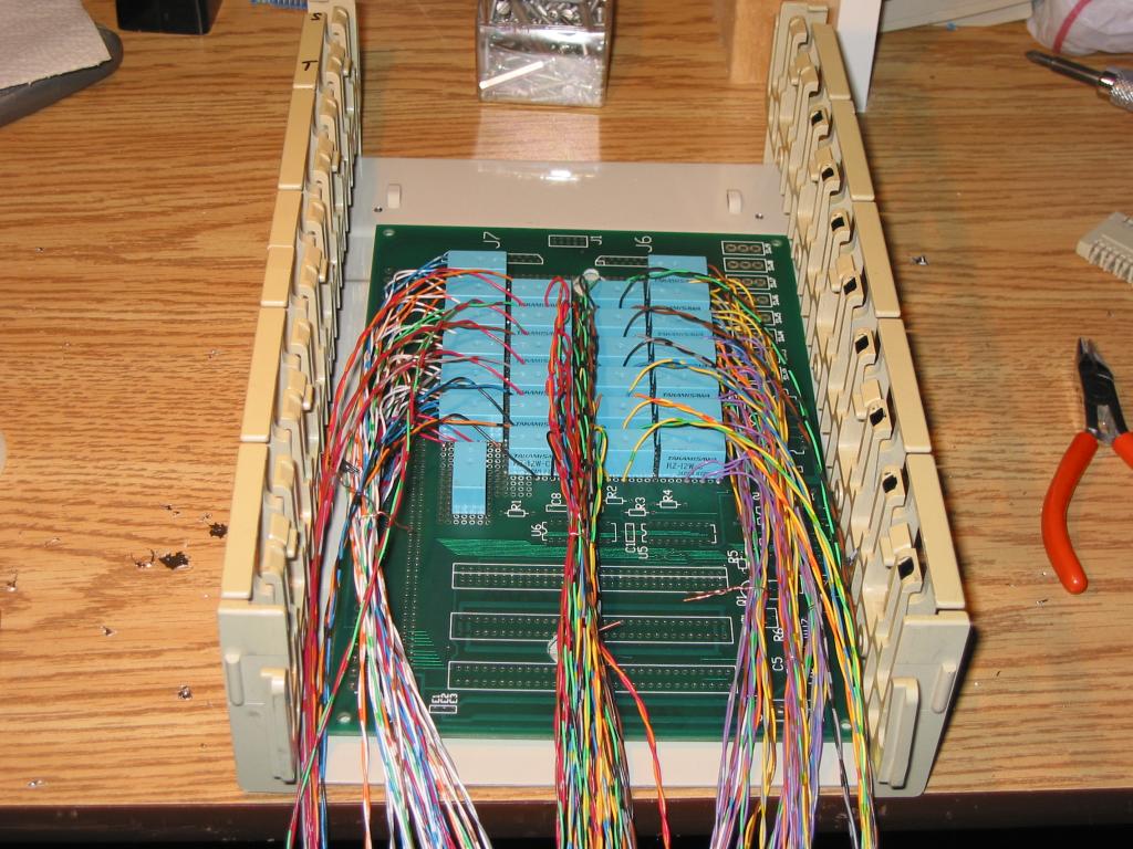
The first step was to find 25 suitable relays, and a PCB that would fit in a standard BIX punchdown rack. I used to work at a company called Datem Ltd which made Bitbus products, and they had a bunch of dDCM901 prototype boards made. This is going back to the mid 1980's, so I figured I could probably safely use one of the prototyping boards without much worry. I modified the PCB by drilling out holes where the BIX rack needed to have screwdriver access to attach it to a wall, and I modified the BIX rack by drilling holes to mount the PCB. I used standoffs between the PCB and the rack to ensure that there would be no shorts. |
Attaching the wires to the BIX punchdown blocks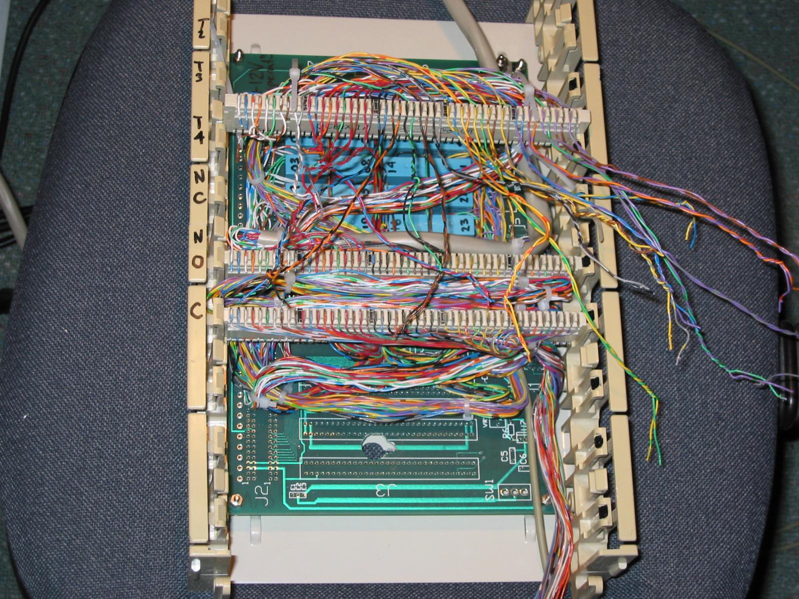 S
M
L
XL
S
M
L
XL
After all the wires were attached to the relays, the next major piece of work was to punch down all of the relay contacts onto the BIX blocks. From top to bottom, the BIX blocks are Normally Closed (NC), Normally Open (NO), and Common (C). This diagram doesn't show the BIX blocks mounted in place yet, that was the next step. |
Final Assembly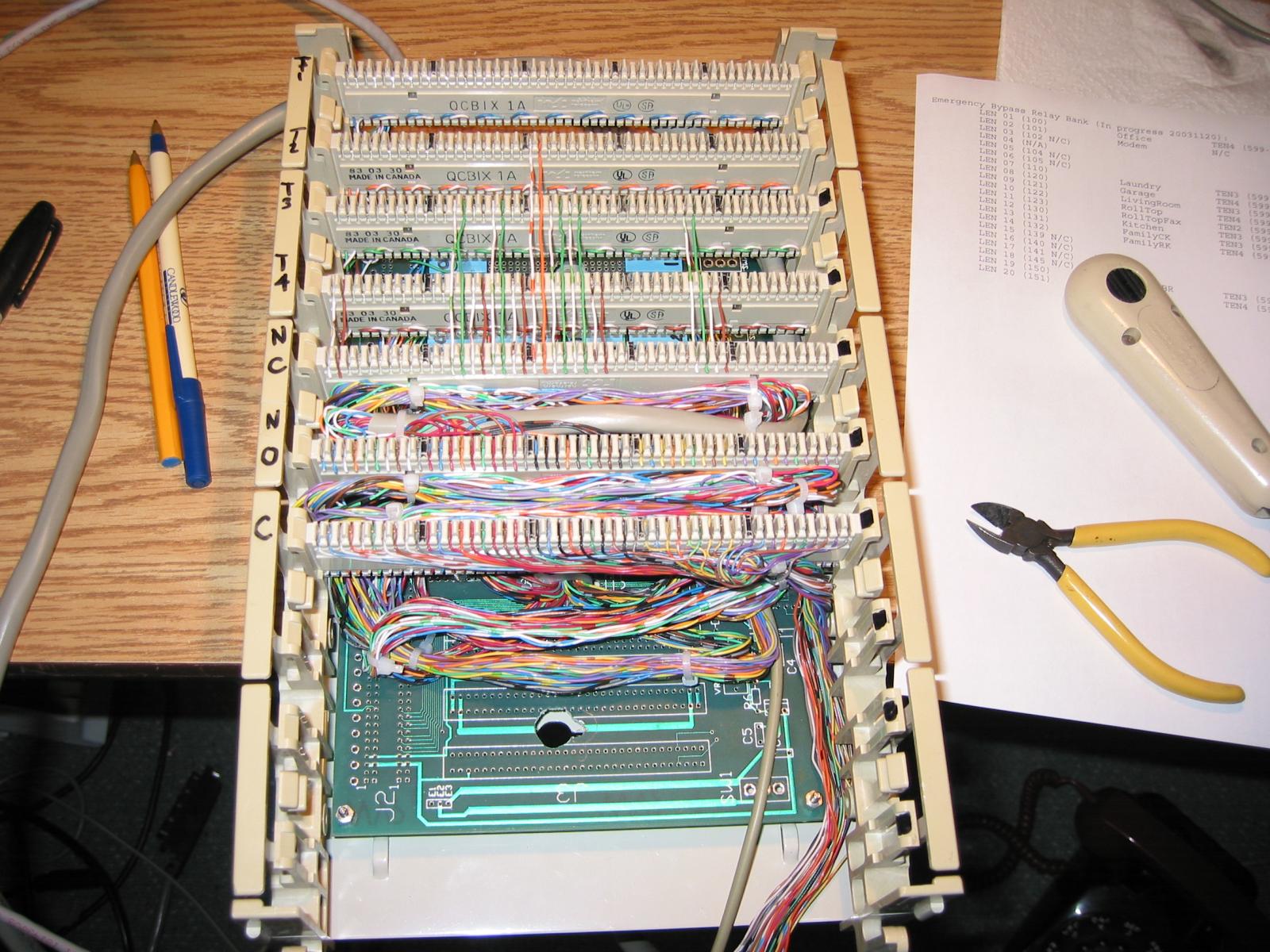 S
M
L
XL
S
M
L
XL
In the final assembly phase, I hardwired the bypass extensions to the trunks. These are the wires shown running vertically between the BIX block marked "NC" and the trunks marked "T2", "T3", and "T4". "T1" isn't used in this case, but I kept it as a spare BIX block in case I get another trunk line going into the house. The connections are done to the NC (Normally Closed) terminals because those are connected to the Common terminal when there is no power -- hence, the trunks will connect through the relays to the NC connections, which are the PABX extensions. On the right hand side of the picture you can see the paper containing the wiring list of extensions and default trunks. |
|